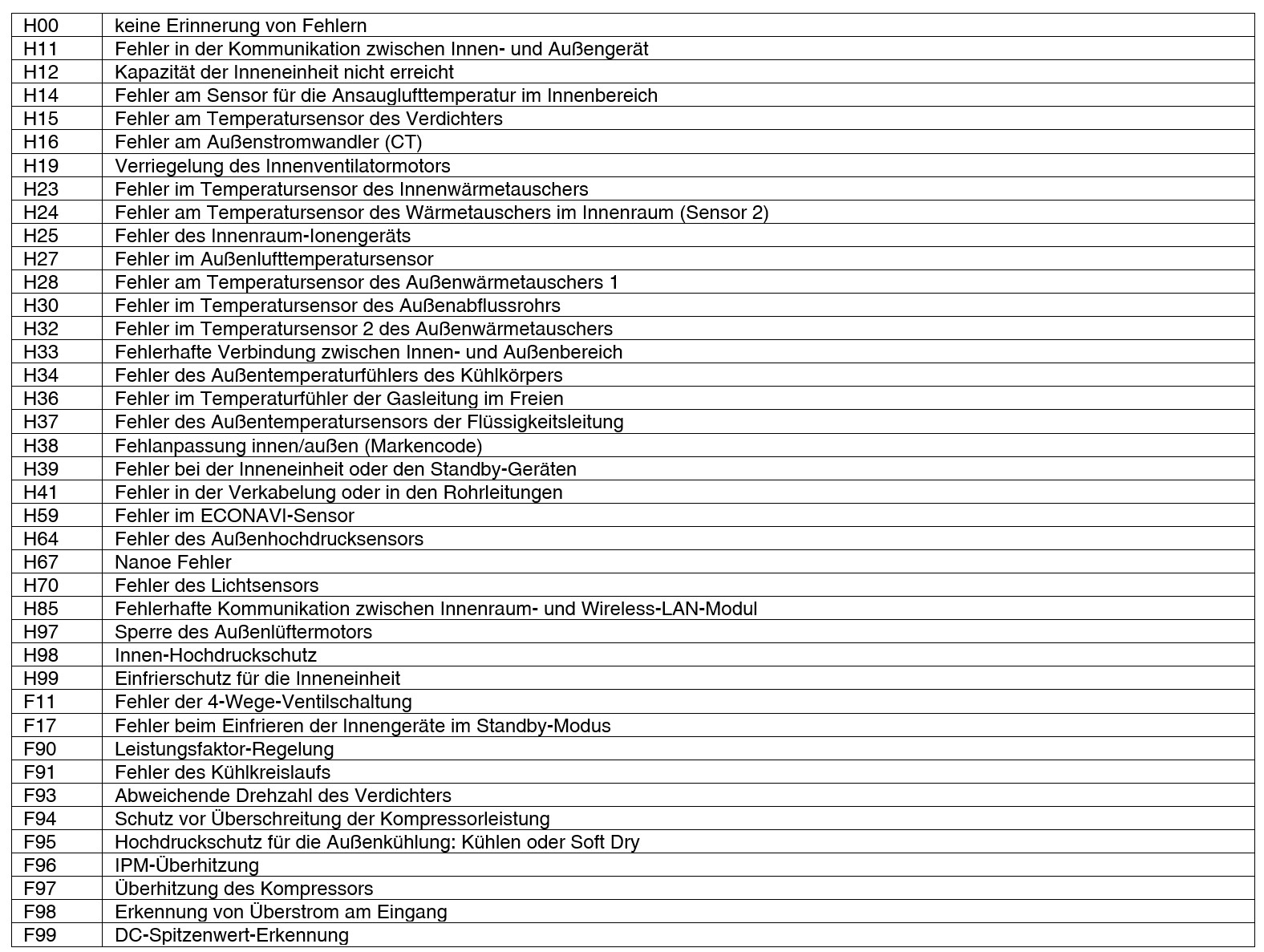
Störungscodes Single-/Multi-Split
Retrieving the fault code with the cable remote control

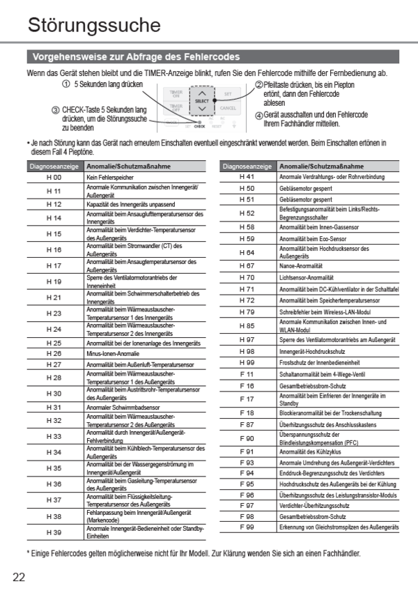
If a fault occurs, CHECK flashes in the display (see figure above).
 When the CHECK button is pressed, an error code from F15 to F44 now appears in the timer field. The air conditioner number appears instead of the set temperature:
 While the fault is displayed, press the TIMER SET button. The fault code is now replaced by an additional code that provides more detailed information on the previously mentioned fault:
Please note:
For single operation, "01" appears as the air conditioner number. In the case of a group set-up, however, a different number can appear. By pressing the "A / C No." the air conditioner number can be called up.
Display of previous fault codes
If the CHECK display is not flashing, press the CHECK button for 5 seconds to display the last or second last fault. You can toggle between the last and second last fault by pressing the TIMER UP or DOWN
  buttons.
Display the last fault code: 1F15 - 1F44
Display the second last fault code: 2F15 - 2F44
The additional code is also called up in this case with the TIMER SET button.
Press the CHECK button again to return to the normal display.
 Press for 5 seconds
the CHECK button:
 Press for additional codes
the TIMER SET button
Retrieving the fault code with the infrared remote control

When a fault occurs, the TIMER LED flashes on the infrared receiver. To query the fault code, the list of fault codes must be run through with the remote control until the indoor unit beeps to indicate that the corresponding fault code has been found. To do this, proceed as follows:
- press the button again. "F 00:00" appears.
- The keys are used to scroll through the digits of the first fault code from "F 0" to "F 9”.
As soon as the number of the first digit matches that of the fault code, a beep sounds in the indoor unit. - The search for the first digit is now completed by pressing the SET button and the cursor jumps to the second digit.
- Steps 3 to 4 are repeated for the second and third digits.
The search for the fault code is completed as soon as a beep sounds at the fourth digit after pressing the buttons or in the indoor unit. The complete fault code can now be read from the display.
F11 4-Wege-Ventil-Schaltstörung
Voraussetzung(en) für die Störmeldung:
- Wenn der Wärmetauscher im Innenraum während des Heizens kalt ist (außer bei Enteisung) oder wenn der Wärmetauscher im Innenraum währen des Kühlens und des Kompressorbetriebs heiß ist, wird das 4-Wege-Ventil als Störung erkannt.
Ursache(n):
- Thermistor des inneren Wärmetauschers
- Störung des 4-Wege-Ventils
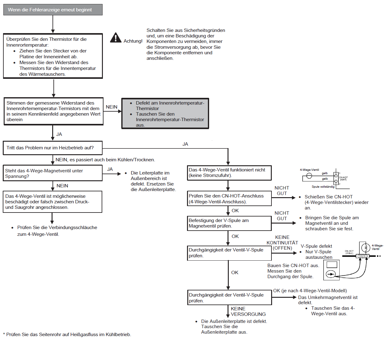
Fehlersuche:
F16-01 Louvre switch (ceiling-mounted units)
| Fault description | Louvre switch (ceiling-mounted units) |
| Preconditions for fault message | The fault occurs when the louvre limit switch does not output any switching signals, even though the louvre motor is activated. |
| Possible causes |
|
| Detection of the fault | See above under “Preconditions for fault message". |
F17 Frostschutz der Standby-Geräte im Innenraum
Voraussetzung(en) für die Störmeldung:
- Wenn der Unterschied zwischen Ansauglufttemperatur im Innenbereich und der Rohrtemperatur im Innenbereich über 10°C liegt oder die Temperatur der Innenraumleitung unter -1,0°C liegt.
- Bemerkung: Wenn das Standby-Innegerät einfriert, überträgt das Außengerät den Fehlercode F17 an das entsprechende Innengerät und H39 an andere Innengeräte.
Ursache(n):
- Falscher Anschluss der Verdrahtung
- Defekter Sensor
- Fehlerhaftes Expansionsventil
Fehlersuche:

F20-01 Indoor unit intake temperature sensor (room temperature sensor)
| Fault description | Indoor unit intake temperature sensor (room temperature sensor) |
| Preconditions for fault message |
|
| Possible causes |
|
| Detection of the fault | See above under “Preconditions for the fault message". |
F20-02 Remote control temperature sensor
| Fault description | Remote control temperature sensor |
| Preconditions for fault message |
|
| Possible causes | Sensor error in the cable remote control. |
| Detection of the fault | See above under “Preconditions for fault message". |
F21-01 Indoor unit heat exchanger temperature sensor
| Fault description | Indoor unit heat exchanger temperature sensor |
| Preconditions for fault message |
|
| Possible causes |
|
| Detection of the fault | See above under “Preconditions for the fault message". |
F26-01Remote data transmission
| Description of fault | Remote data transmission |
| Preconditions for fault message | No response from the remote control for 3 minutes. |
| Possible causes |
|
| Detection of the fault | See above under “Preconditions for the fault message”. |
F30-01 System problem
| Description of fault | System problem |
| Preconditions for fault message | The performance of the indoor unit (or the sum of the indoor units) does not match the outdoor unit (the total output of the connected indoor units is below the minimum power limit or above the maximum power limit of the outdoor unit). |
| Possible causes | Too many indoor units or indoor unit (s) of incorrect power connected. |
| Detection of the fault | Immediate |
F30-02 Phase open or reversed
| Description of the fault | Phase open or reversed |
| Preconditions for fault message | The system detects a phase that does not exist or is inverted. |
| Possible causes |
|
F31-01 Suction pressure shutdown
| Description of the fault | Suction pressure shutdown |
| Preconditions for fault message |
|
| Possible causes |
|
F31-02 High pressure shutdown
| Description of the fault | High pressure shutdown |
| Preconditions for fault message | The heat exchanger temperature is above the limit, which indicates an increase in high pressure. |
| Possible causes |
|
| Detection of the fault | The heat exchanger temperature must be above the limit three times within 30 minutes for one minute each. |
F32-06 Switch valve
| Description of the fault | Switch valve |
| Preconditions for fault message | When the compressor is running, the indoor unit heat exchanger is too cold (<5°C) for 5 minutes in heating mode (except when defrosting) or too warm in cooling mode (>45°C). |
| Possible causes |
|
| Detection of the fault | The above preconditions are met three times within 30 minutes. |
F32-08 Freezing of the indoor unit heat exchanger
| Description of the fault | Freezing of the indoor unit heat exchanger |
| Preconditions for fault message | The temperature of the indoor unit heat exchanger is below a certain value for a certain period. |
| Possible causes |
|
F32-09 Inverter protection (DC overcurrent
| Inverter protection (DC overcurrent) | Preconditions) |
| for fault message | Inverter DC overcurrent signals are detected during start-up and in cooling and heating mode. |
| Possible causes |
|
| Detection of the fault |
|
F32-10 Refrigeration problem
| Description of the fault | Refrigeration problem |
| Preconditions for fault message | One of the following conditions must be met within seven minutes of the compressor starting up in cooling mode:
|
| Possible causes |
|
| Detection of the fault | See under “Preconditions for fault message”. |
F32-03 Inverter protection (low DC voltage)
| Description of the fault | Inverter protection (low DC protection) |
| Preconditions for fault message | DC voltage <180 V in 40 ms after tightening RY_AC (RY_PWR). |
| Possible causes |
|
| Detection of the fault | Immediate. |
F32-04 Overheating protection of the power transistor (IPM)
| Description of the fault | Overheating protection of the power transistor (IPM) |
| Preconditions for fault message | Elevated temperature of the power transistor module (IPM) (5 Sec. > 95°C). |
| Possible causes |
|
| Detection of the fault | 4 occurrences within 30 minutes. |
F32-05 Compressor overcurrent protection
| Description of the fault | Compressor overcurrent protection |
| Preconditions for fault message | The current consumption is exceptionally high during compressor operation. |
| Possible causes |
|
| Detection of the fault | 3 occurrences within 30 minutes. |
F32-06 Hot gas temperature protection
| Description of the fault | Hot gas temperature protection |
| Preconditions for fault message | In cooling or heating mode, the hot gas temperature exceeds 110°C, the compressor is switched off. If it falls below 105°C, the compressor starts again after 3 minutes. |
| Possible causes |
|
| Detection of the fault | 3 occurrences within 60 minutes. |
F32-08 Inverter protection (reactive current compensation)
| Description of the fault | Inverter protection (reactive current compensation) |
| Preconditions for fault message | Incorrect signals in the reactive current compensation circuit (PFC circuit). |
| Possible causes |
|
| Detection of the fault | The problem has existed for three minutes. |
F32-09 Inverter protection (DC overcurrent
| Description of the fault | Inverter protection (DC overcurrent) |
| Preconditions for fault message | Inverter DC overcurrent signals are detected during start-up and in cooling and heating mode. |
| Possible causes |
|
| Detection of the fault |
|
F32-10 Incorrect compressor speed
| Description of the fault | Incorrect compressor speed |
| Preconditions for fault message | The compressor speed does not correspond to the speed signal. |
| Possible causes |
|
| Detection of the fault | 4 occurrences within 20 minutes. |
F35 DC fan motor blocked.
Priority check: DC fan motor
No obvious fault: Please contact one of our technicians
F40-01 Outside temperature sensor
| Description of the fault | Outside temperature sensor |
| Preconditions for fault message | A temperature of <-33.4°C or > 124°C is determined for 5 seconds. |
| Possible causes |
|
F40-11 Compressor suction gas temperature sensor
| Description of the fault | Compressor suction gas temperature sensor |
| Preconditions for fault message | A temperature of <-50.5°C or > 103.7°C is detected for 5 seconds. |
| Possible causes |
|
F40-21 Compressor suction gas temperature sensor
| Description of the fault | Compressor suction gas temperature sensor |
| Preconditions for fault message | A temperature of <-50.5°C or > 103.7°C is detected for 5 seconds. |
| Possible causes |
|
F40-31 Defrost temperature sensor
| Description of the fault | Defrost temperature sensor |
| Preconditions for fault message | A temperature of <-50.5°C or > 103.7°C is detected for 5 seconds. |
| Possible causes |
|
F40-51 Compressor hot gas temperature sensor
| Description of the fault | Compressor hot gas temperature sensor |
| Preconditions for fault message | With the compressor running (except start-up), a temperature <-4.5°C or > 201.8°C is detected for 5 seconds. |
| Possible causes |
|
F41 -02 High pressure switch open
| Description of fault | High pressure switch open |
| Preconditions for fault message | The high pressure switch is open for one minute while the compressor is stopped. |
| Possible causes |
|
F41 - 12 Low pressure switch -open
| Description of the fault | Low pressure switch (Not Inverter) |
| Preconditions for fault message | The low pressure switch is open for one minute while the compressor is stopped. |
| Possible causes |
|
F42 Transformer
| Description of the fault | Transformer in outdoor unit is open |
| Preconditions for fault message | The power consumption is too low for 60 seconds after the compressor starts. |
| Possible causes |
|
| Detection of the fault | 1 minute after compressor start:
|
F44: Inverter protection
| Description of the fault | Inverter protection (Power transistor module temperature sensor) |
| Preconditions for fault message | The temperature sensor in the circuit of the power transistor module determines an elevated temperature. |
| Possible causes: | Faulty outdoor unit circuit board. |
F90
Voraussetzung(en) für die Störmeldung:
- Aufrechterhaltung des Gleichspannungspegels für den Leistungstransistor.
- Zur Erkennung eines hohen Gleichspannungspegels nach der Gleichrichtung.
Ursache(n):
- Während des Starts und des Heiz- und Kühlbetriebs, wenn die Schutzschaltung für die Leistungsfaktorkorrektur auf der Hauptplatine des Außengeräts eine anormale Gleichspannungspegel für die Leistungstransistoren erkennt.
- Wenn die erkannte Gleichspannung NIEDRIG ist, schaltet der Regler die Transistoren ein, um den Gleichstrompegel zu erhöhen.
- Wenn die erkannte Gleichspannung HOCH ist (391V DC - 425 V DC), sendet der Regler ein akrives NIEDRIG-Signal, um das Relais RY-C auszuschalten.
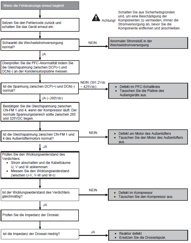
Fehlersuche:
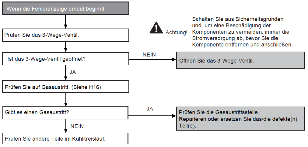
F91
Voraussetzung(en) für die Störmeldung:
- Der Eingangsstrom ist niedrig, während der Verdichter mit einer höheren als der eingestellten Frequenz läuft.
Ursache(n):
- Gasmangel
- 3-Wege-Ventil geschlossen
Fehlersuche:
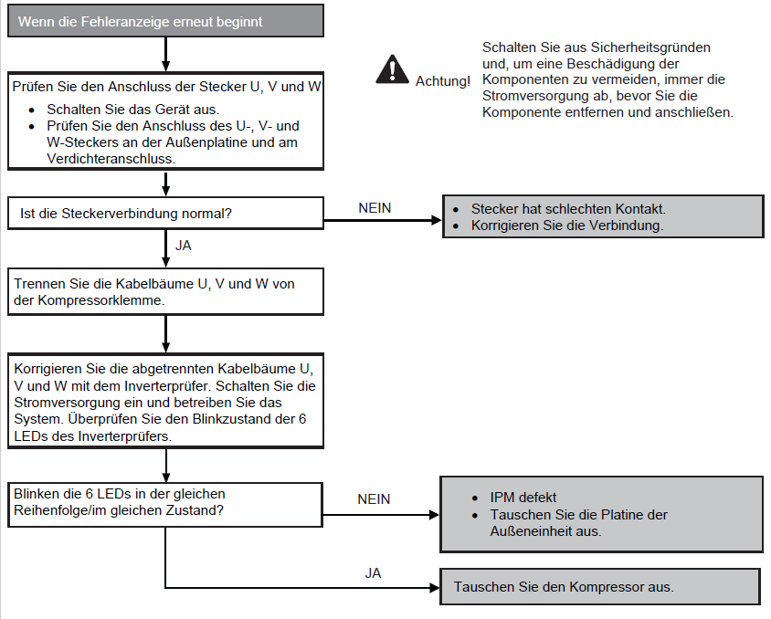
F93
Voraussetzung(en) für die Störmeldung:
- Die falsche Kompressor Drehzahl wird duch Überprüfung des Verdichterbetriebszustands über den Positionserkennungskreis erkannt.
Ursache(n):
- Verdichterklemme nicht angeschlossen
- Defekte Außenleiterplatte
- Defekter Verdichter
Fehlersuche:
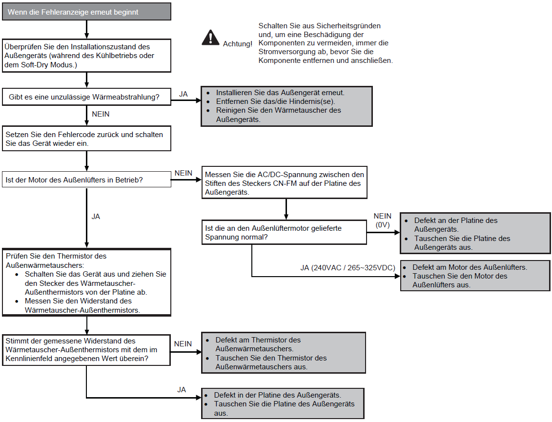
F95
Voraussetzung(en) für die Störmeldung:
- Während des Kühl- oder Soft-Dry-Betriebs, wenn der Wärmetauscher des Außengeräts vom Thermistor des Außengeräts eine hohe Temperatur erfasst.
Ursache(n):
- Kurzschluss des heißen Auslassluftstrom
- Defekt am Motor des Außenlüfters
- Defekter Thermistor des Außenwärmetauschers
- Defekt an der Platine des Außengeräts
Fehlersuche:
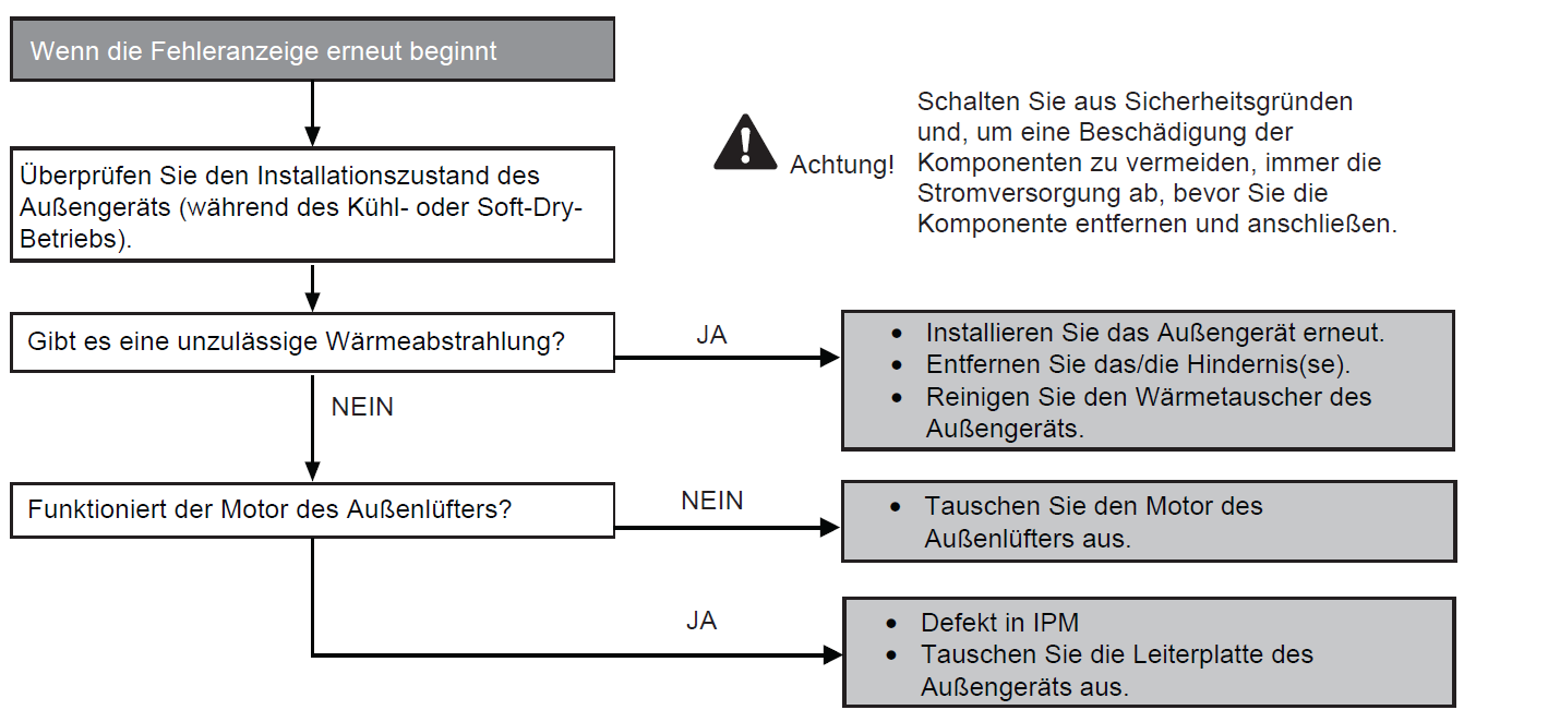
F96
Voraussetzung(en) für die Störmeldung:
- Während des Kühl- und Heizbetriebs, wenn die IPM-Temperaturdaten (100°C) vom IPM-Temperatursensor erfasst werden.
- Nur bei Multi-Modellen:
- Überhitzung des Kompressors: Während des Kühl- und Heizbetriebs, wenn der Verdichter OL aktiviert wird.
- Überhitzung des Kühlkörpers: Während des Kühl- und Heizbetriebs, wenn der Temperatursensor des Kühlkörpers eine Temperatur von 90°C feststellt.
Ursache(n):
- Kurzschluss des heißen Auslassluftstroms
- Defekt am Außenlüftermotor
- Defekt am internen Schaltkreis des IPM
- Defekter IPM-Temperatursensor
- Nur bei Multi-Modellen:
- Kompressor-OL-Stecker hat schlechten Kontakt
- Verdichter OL defekt
Fehlersuche:
F97
Voraussetzung(en) für die Störmeldung:
Während des Kühl- und Heizbetriebs, wenn die Temperaturdaten des Verdichterbehälters (112°C) vom Verdichterbehältertemperatursensor erfasst werden.
Ursache(n):
- Defekter Temperatursensor im Verdichterbehälter
- 2/3-Wegeventil geschlossen
- Kältemittelmangel (Kältemittelleckage)
- Defekte Leiterplatte des Außengeräts
Fehlersuche:

F98
Voraussetzung(en) für die Störmeldung:
Während des Kühl- und Heizbetriebs, wenn ein Eingangsüberstrom (X-Wert in Total Running Current Control) durch Überprüfung des vom Stromwandler (CT) erfassten Eingangsstromwerts bei laufendem Kompressor erkannt wird.
Ursache(n):
- Überschüssiges Kältemittel.
- Defekte Leiterplatte des Außengeräts.
Fehlersuche:

F99
Voraussetzung(en) für die Störmeldung:
Während des Starts und des Betriebs von Kühlung und Heizung, wenn der interne DC-Spitzenwert-Erkennungsschaltkreis im Außenbereich DC-Spitzenwertdaten vom Wechselrichter empfängt.
Ursache(n):
- DC-Stromspitze aufgrund eines Verdichterausfalls.
- Gleichstromspitze durch defekte(n) Leistungstransistor(en).
- Gleichstromspitze aufgrund einer defekten Leiterplatte des Außengeräts.
- Gleichstromspitze aufgrund eines Kurzschlusses.
Fehlersuche:

H11
Voraussetzung(en) für die Störmeldung:
- Während der Inbetriebnahme und des Heiz- und Kühlbetriebs wird geprüft, ob die vom Außengerät empfangenen Daten bei der Signalübertragung des Innengeräts normal sind.
Ursache(n):
- Defekte Leiterplatte des Innengeräts
- Defekte Leiterplatte des Außengeräts
- Signalübertragungsfehler Innengerät-Außengerät aufgrund eines Verdrahtungsfehlers
- Signalübertragungsfehler Innengerät-Außengerät aufgrund eines Drahtbruchs in den Verbindungsleitungen zwischen Innen- und Außengerät
Fehlersuche:

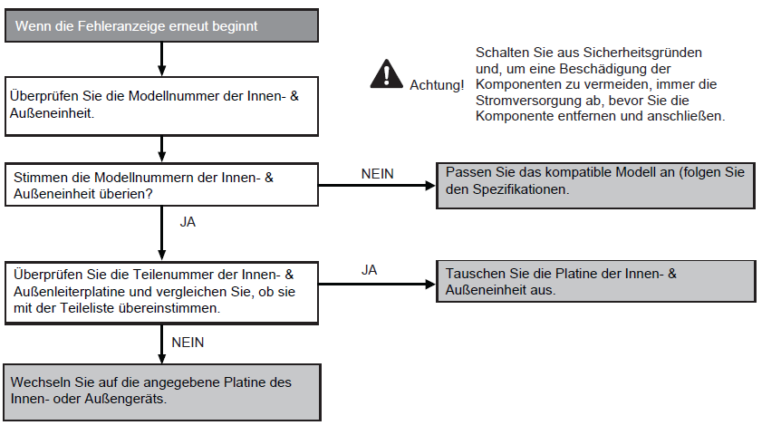
H12
Voraussetzung(en) für die Störmeldung:
- Während der Inbetriebnahme erscheint ein Fehlercode, wenn verschiedene Typen von Innen- und Außengeräten zusammengeschaltet sind.
Ursache(n):
- Falsche Modelle zusammengeschaltet
- Falsche Innengerät- oder Außengerät-Leiterplatten montiert
- Leiterplatten des Inne- oder Außengeräts sind defekt
- Signalübertragungsfehler des Innen- und Außengeräts aufgrund falscher Verdrahtung
- Signalübertragungsfehler des Innen- und Außengeräts aufgrund eines Bruchs von Draht 3 in den Verbindungskablenz zwischen Innen- und Außengerät
Fehlersuche:
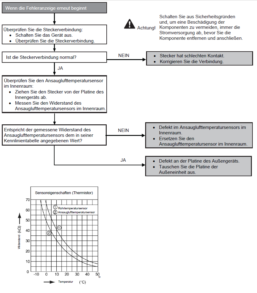
H14
Voraussetzung(en) für die Störmeldung:
- Während der Inbetriebnahme und des Kühl- und Heizbetriebs werden die vom Raumlufttemperaturfühler erfassten Temperaturen zur Beestimmung von Sensorfehlern verwendet.
Ursache(n):
- Fehlerhafte Steckerverbindung
- Defekter Sensor
- Defekte Leiterplatte
Fehlersuche:
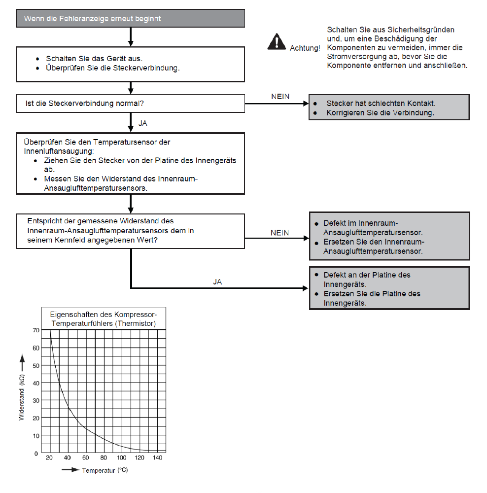
H15
Voraussetzung(en) für die Störmeldung:
- Während der Inbetriebnahme und des Kühl- und Heizbetriebs werden die vom Außenverdichter-Temperatursensor erfassten Temperaturen zur Bestimmung von Sensorfehlern verwendet.
Ursache(n):
- Fehlerhafte Steckerverbindung
- Defekter Sensor
- Defekte Leiterplatte
Fehlersuche:
H16
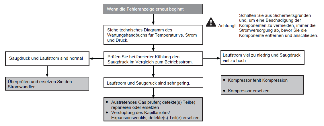
Voraussetzung(en) für die Störmeldung:
- Ein vom Stromwandler erfasste Eingangsstrom liegt unter dem Schwellenwert, wenn der Verdichter 3 Minuten Lang bei einem bestimmten Frequenzwert betrieben wird.
Ursache(n):
- Gasmangel
- Defekter Stromwandler
- Defekte Außenplatine
Fehlersuche:
H19
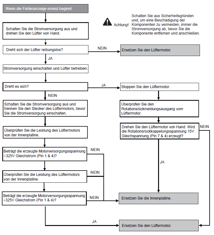
Voraussetzung(en) für die Störmeldung:
- Die vom Hall-Sensor während des Betriebs des Lüftermotors erfasste Drehzahl wird verwendet, um einen abnormalen Lüftermotor zu bestimmen.
Ursache(n):
- Kurzschlusse in der Wicklung des Lüftermotors
- Drahtbruch innerhalb des Lüfterrmotors
- Kabelbruch in der Lüftermotorleitung
- Fehlfunktion des Hall-Sensors
- Defekte Innengeräteplatine
Fehlersuche:
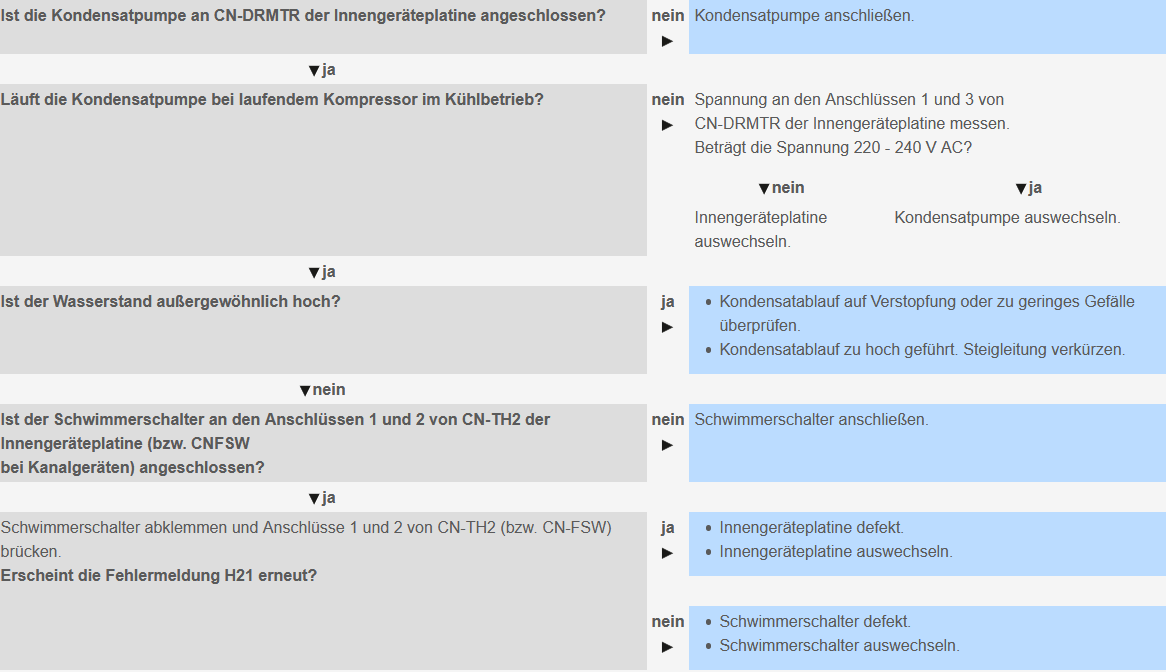
H21: Float switch in the indoor unit
Priority check: Float switch
Possible causes:
- Condensate pump clogged or no slope
- Faulty condensate pump (CN-DRMTR).
- Float switch not connected (CN-TH2, connections 1 and 2 for cassettes and CN-FSW, Connections 1 and 3 for duct units).
- Float switch defective (blocked in the open position).
- Faulty indoor unit ciruit board.
- Fan motor mechanically blocked.
To check and remedy see figure.
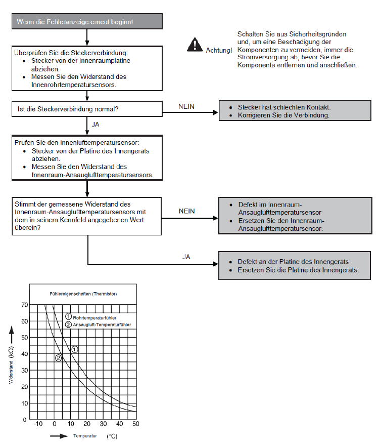
H23
Voraussetzung(en) für die Störmeldung:
- Während der Inbetriebnahme und des Kühl- und Heizbetriebs werden die vom Innenraum-Wärmetauschertemperatursensor erfassten Temperaturen zur Bestimmung von Sensorfehlern verwendet.
Ursache(n):
- Fehlerhafter Anschluss des Steckers
- Defekter Sensor
- Defekte Leiterplatte
Fehlersuche:

H24
Voraussetzung(en) für die Störmeldung:
- Während der Inbetriebnahme und des Heiz- und Kühlbetriebs werden die vom Temperatursensor des Innenraum-Wärmetauschers-Temperatursensor erfassten Temperaturen zur Bestimmung von Sensorfehlern verwendet.
Ursache(n):
- Fehlerhafter Anschluss des Steckers
- Defekter Sensor
- Defekte Leiterplatte
Fehlersuche:
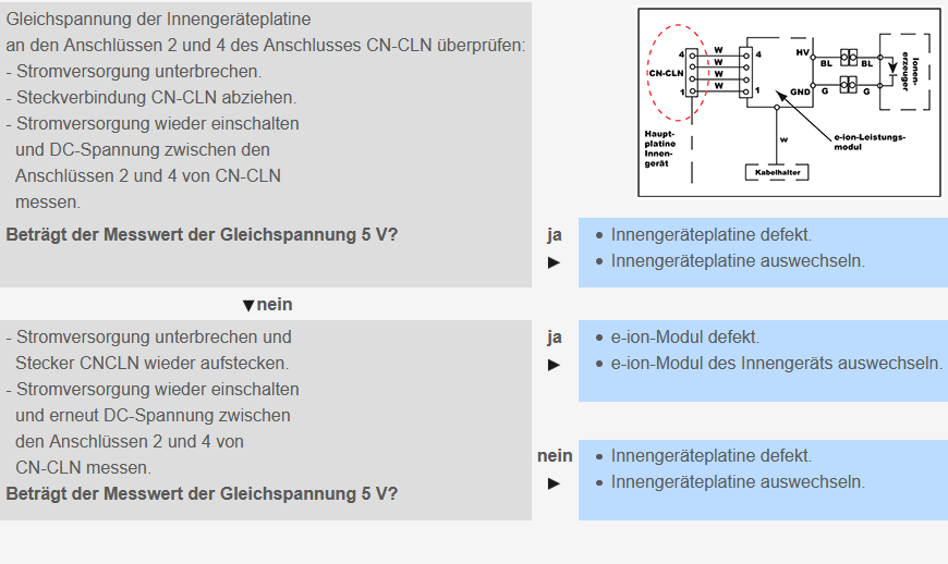
H25 E-ion power module malfunction
Priority check:
- Circuit board indoor unit
- e-ion power module
Possible causes:
- Faulty e-ion module (high-voltage generator for positive charging of the filters).
- Faulty circuit board.
- Faulty connection or wiring (open or short-circuited).
For checking and rectification see figure.
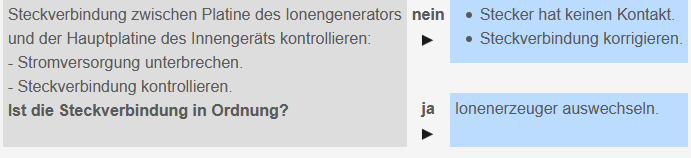
H26 Air ioniser fault
Priority check:
- Indoor unit circuit board
- Ioniser
Possible causes:
- Faulty air ioniser circuit.
- Faulty plug connection.
- Faulty circuit board.
To check and rectify see picture.
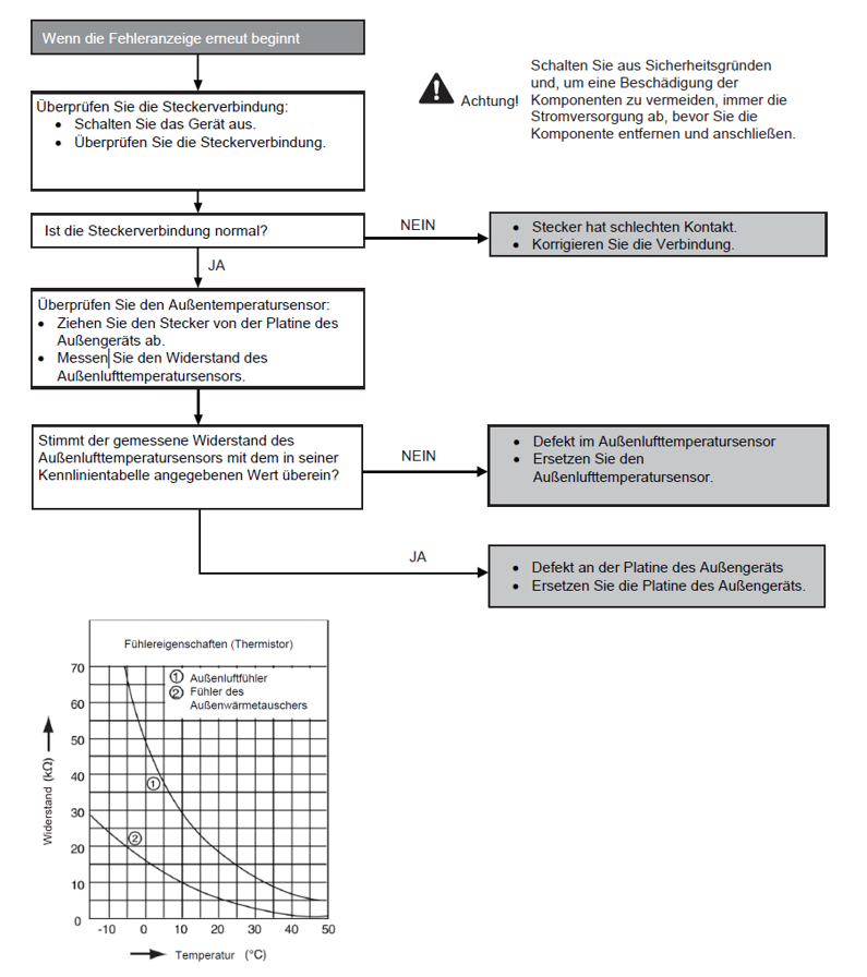
H27
Voraussetzung(en) für die Störmeldung:
- Während der Inbetriebnahme und des Heiz- und Kühlbetriebs werden die vom Außenlufttemperatursensor erfassten Temperaturen zur Bestimmung von Sensorfehlern verwendet.
Ursache(n):
- Fehlerhafte Steckerverbindung
- Defekter Sensor
- Defekte Leiterplatte
Fehlersuche:
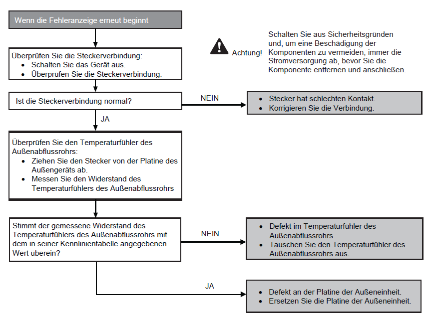
H28
Voraussetzung(en) für die Störmeldung:
- Während der Inbetriebnahme und des Heit- und Kühlbetriebs werden die vom Außenrohrtemperatursensor erfassten Temperaturen zur Bestimmung von Sensorenfehlern verwendet.
Ursache(n):
- Fehlerhafte Steckerverbindung
- Defekter Sensor
- Defekte Leiterplatte
Fehlersuche:
H30
Voraussetzung(en) für die Störmeldung:
- Während der Inbetriebnahme und des Heiz- und Kühlbetriebs werden die vom Außenlufttemperatursensor erfassten Temperaturen zur Bestimmung von Sensorfehlern verwendet.
Ursache(n):
- Fehlerhafte Steckerverbindung
- Defekter Sensor
- Defekte Leiterplatte
Fehlersuche:
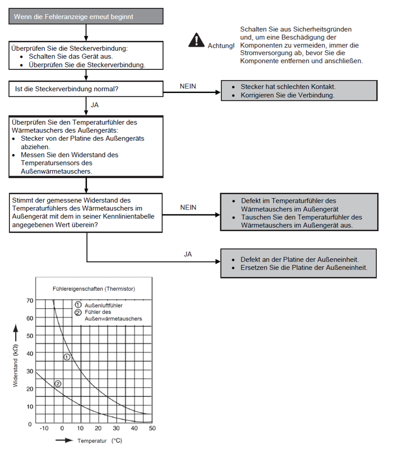
H32
Voraussetzung(en) für die Störmeldung:
- Während der Inbetriebnahme und des Heiz- und Kühlbetriebs werden die vom Außentemperatursensor des Wärmetauschers erfassten Temperaturen zur Bestimmung von Sensorfehlern verwendet.
Ursache(n):
- Fehlerhafte Steckerverbindung
- Defekter Sensor
- Defekte Leiterplatte
Fehlersuche:

H33
Voraussetzung(en) für die Störmeldung:
- Die Versorgungsspannung wird durch die Innen-/Außenübertragung für ihren Bedarf erkannt.
Ursache(n):
- Falsche Modelle zusammengeschaltet
- Falsche Platiten für Innen- und Außengerät verwendet
- Defekte Platine des Innen- oder Außengeräts
Fehlersuche:
H34
Voraussetzung(en) für die Störmeldung:
- Während der Inbetriebnahme und des Heiz- und Kühlbetriebs werden die vom Außentemperatursensor des Kühlkörpers erfassten Temperaturen zur Bestimmung von Sensorfehlern verwendet.
Ursache(n):
- Fehlerhafte Steckerverbindung
- Defekter Sensor
- Defekte Leiterplatte
Fehlersuche:
H36
Voraussetzung(en) für die Störmeldung:
- Während der Inbetriebnahme und des Heiz- und Kühlbetriebs werden die vom Gasaußentemperatursensor erfassten Temperaturen zur Bestimmung von Sensorfehlern verwendet.
Ursache(n):
- Fehlerhafte Steckerverbindung
- Defekter Sensor
- Defekte Leiterplatte
Fehlersuche:

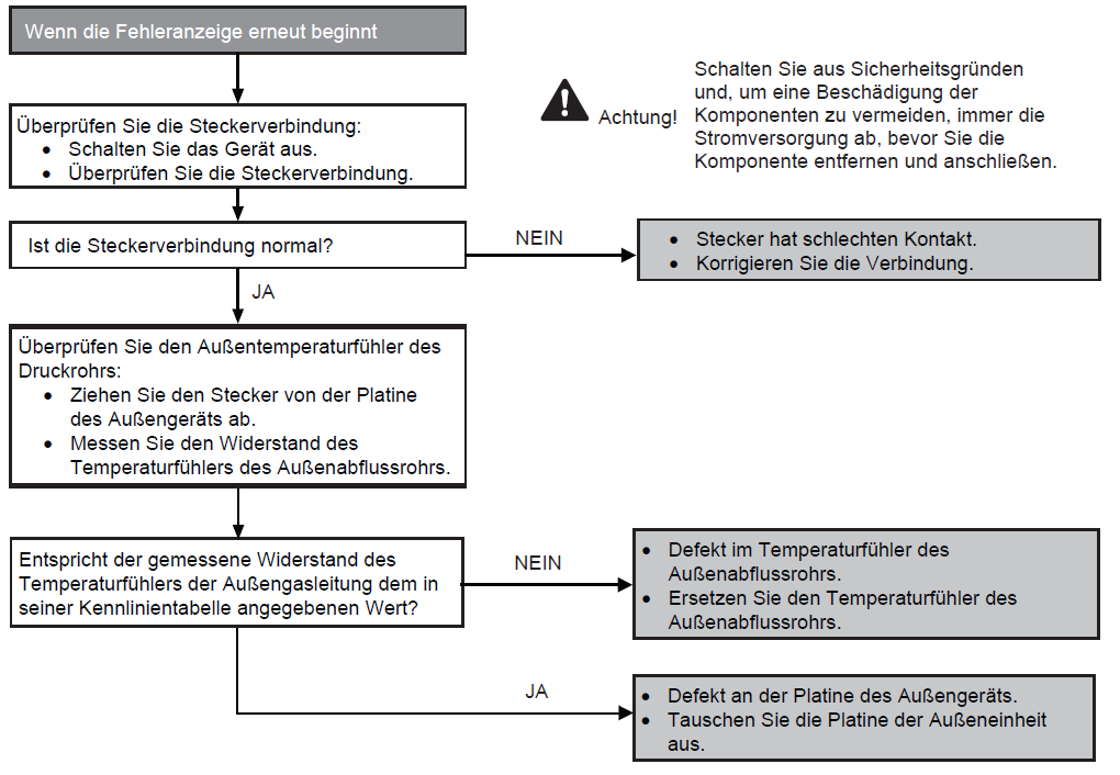
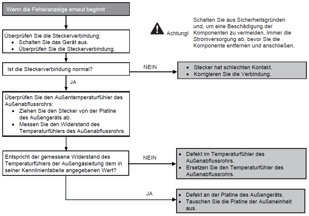
H37
Voraussetzung(en) für die Störmeldung:
- Während der Inbetriebnahme und des Heiz- und Kühlbetriebs werden die vom Flüssigkeits-Temperaturfühler des Außengerät erfassten Temperaturen zur Bestimmung von Sensorfehlern verwendet.
Ursache(n):
- Fehlerhafte Steckerverbindung
- Defekter Sensor
- Defekte Leiterplatte
Fehlersuche:
H97
Voraussetzung(en) für die Störmeldung:
- Die vom Hall-Sensor während des Betriebs des Lüftermotors erfasste Drehzahl wird verwendet, um einen defekten Lüftermotor zu bestimmen.
Ursache(n):
- Kurzschluss in der Wicklung des Lüftermotors
- Drahtbruch im Lüftermotor
- Kabelbruch in der Lüftermotorleitung
- Fehlfunktion des Hall-Sensors
- Defekte Leiterplatte des Außengeräts
Fehlersuche: