- Products
- Mounting material
- Connection adapters
- Mounting couplings
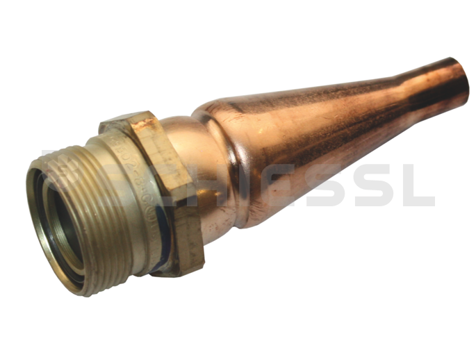
- Male coupling half 5502-10-8 without flange and cap
Mounting couplings
Male coupling half 5502-10-8 without flange and cap


Icon. Image similar to product.

Order No.: 721.3414
Manufacturer number: 5502-10B-08
Manufacturer: Aeroquip
More in this category: Mounting couplings
One click to the most important information:
Description
The Aeroquip 5500 series self-sealing couplings have been designed for joining refrigerant lines in air conditioning and refrigeration systems. The tried and tested Aeroquip design guarantees that refrigerant flows unimpeded through the joint with a minimal loss of pressure. They have been designed for secure storage and simple onsite installation of air conditioning and refrigeration system components pre-filled with refrigerant in construction, vehicle construction and industry. The 5500 coupling has just one mechanical sealing element. The coupling halves are soldered directly to the pipe (inch standard), joints using threaded adapters are therefore not possible. Installation of the coupling into a partition panel is done using a simple flange. Both couplings are connected using a hexagonal nut. Fully seal both coupling halves while separated. Loss of refrigerant on one side and entry of air and dirt into the refrigerant circuit on the other are practically impossible. Dust caps and dust plugs available for protecting coupling halves; they also function as an additional seal during storage and transport. The self-sealing function of the seals allows air conditioning components to be filled during production. This means that time-consuming system evacuation and filling is avoided at the installation location.
Installation
Installation
- Drill holes into the compartment or plate for attaching the 5502 coupling halves and for the screws for flange mounting. Remove the dust cap before positioning. Mount the inner coupling halves by pushing the flange over the coupling end (before soldering the pipe) and use self-tapping screws to attach to the wall. Replace the dust cap before soldering.
- When soldering the coupling halves to pipe ends, be sure to follow the step below in order to maintain a gas proof seal. Blow down the copper halves with nitrogen from the soldering side before commencing soldering. The soldering location must be bathed in nitrogen inside the coupling to prevent scaling while soldering. Place coupling halves in flowing water, 20-25 mm deep, so that the rubber seals do not get burnt nor the soldered seam of membrane loses its seal. If working conditions make it impossible to cool by immersion, then wrap a damp cloth around the coupling, this can be repeatedly dampened during the soldering process. Solder “4003 U” should be used. The melting temperature is between 595 and 630 °C, the required flux is already placed around the metallic solder as a cover. When properly worked, this solder does not need cleaning. A small single-flame burner is sufficient as a heat source for soldering without discolouration. A double-flame torch is recommended, however, as its two jets ensure a more even heat distribution around the pipe being soldered.
- Visually inspect solder connections and replace end cap/plug.
- If necessary, clean the thread on both coupling halves with a clean cloth to prevent dirt and moisture getting into the system.
- Then screw on the cap nut by hand until the thread is tight and then use two perfectly sized or adjustable spanners to tighten further until there is considerable resistance. Axially mark hexagon bolt and bulkhead wall as well as counter cap nut and further tighten the cap nut until the markings are positioned 1/4 turn (approx. 90°) apart. This ensures a leakproof metallic connection between both halves of the coupling.
Accessories / Replacement parts
-
Assembly flange
-
Dust cap
Technical data
Dimensions
Basic clutch size
-8
General information
Construction
Kupplungshälfte männlich
Pipe connections
Pipe dimension
5/8 Zoll
Technical modifications reserved. Product images may differ from the actual product and are meant for demonstration purposes only. Absolutely no liability can be assumed for possible indication errors and errors in the manufacturers’ information.
Customers also bought...
Recently viewed products
Loading
Login now for complete access
To login
Available in another country - please contact your local office
Loading


